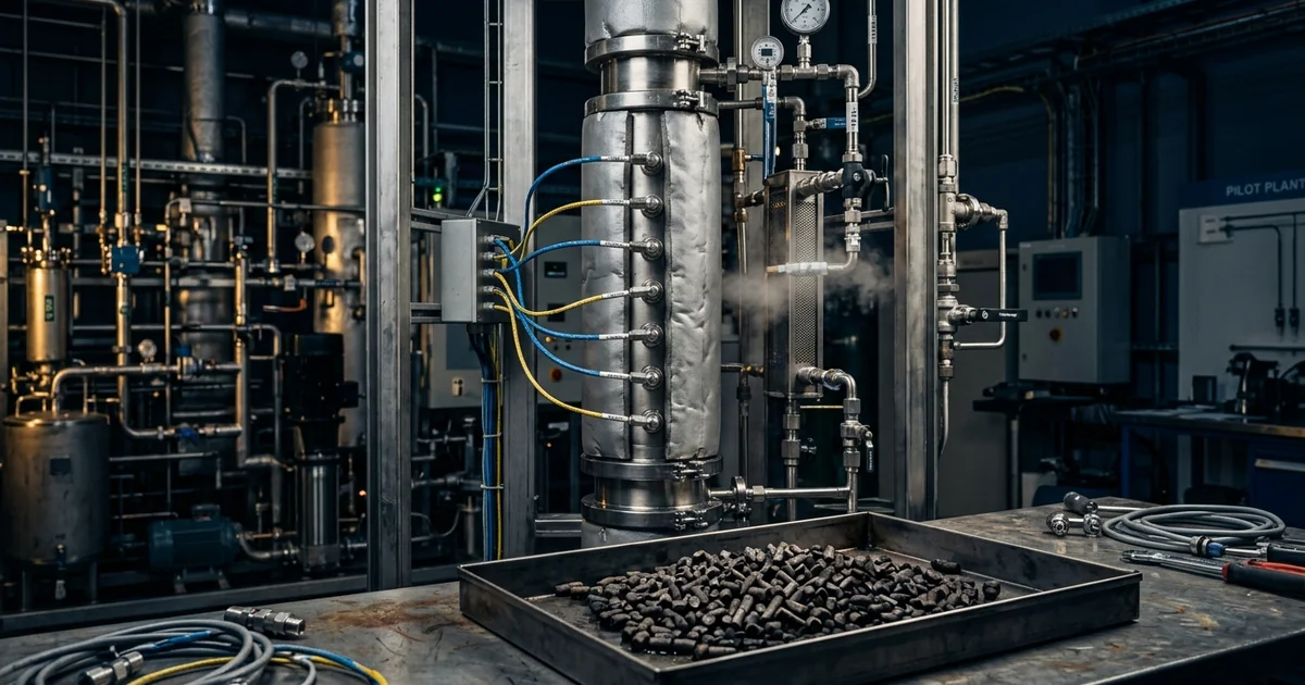
A fixed-bed hydrogenation that converted cleanly for weeks begins to lose conversion, and operators raise the temperature to hold rate. Nothing has failed, no alarm has tripped, and the feedstock certificate reads the same as last month. This is catalyst deactivation: the gradual loss of activity or selectivity while a catalyst works, and it sets campaign length, turnaround timing and catalyst cost per tonne of product. Misread the cause and a regeneration that would have cured coking will instead sinter a poisoned catalyst beyond recovery. This guide sets out the recognised catalyst deactivation mechanisms and shows how to tell them apart from data a plant already collects. It also explains what regeneration can and cannot restore, and how to design for catalyst life before scale-up rather than after. It reflects the reasoning we apply in our chemical reaction engineering work.
Catalyst Deactivation Mechanisms: Why Catalysts Lose Activity
Every working catalyst deactivates eventually, so the useful question is how fast and by which route, not whether. The route decides what a plant can do about it, because some losses reverse with a treatment and others set the replacement date. Argyle and Bartholomew's review of heterogeneous catalyst deactivation and regeneration groups the causes into chemical, thermal and mechanical classes. Bartholomew's earlier paper in Applied Catalysis A resolves these into six intrinsic types of catalyst deactivation, listed below.
- Poisoning — impurities chemisorb strongly on active sites and block them, arriving with the feed or forming as a by-product of the reaction.
- Fouling and coking — carbonaceous or polymeric deposits cover sites and block pores, and in packed beds they also raise pressure drop.
- Thermal degradation and sintering — heat makes active metal crystallites grow and supports lose area, so less active surface stays exposed.
- Vapour compound formation — the active phase forms a volatile species with a reactant or contaminant and leaves the reactor with the product stream.
- Vapour–solid and solid–solid reactions — the active phase reacts with the support, a promoter or a feed component to form an inactive compound.
- Attrition and crushing — mechanical stress breaks particles into fines, which shrinks catalyst inventory and blocks filters and bed voids.
Catalyst deactivation kinetics is usually expressed through the activity, a(t): the rate on catalyst aged for time t, divided by the rate on fresh catalyst under the same conditions. A common empirical form is da/dt = −kdam, where kd is the deactivation rate constant and m is the deactivation order. First-order decay (m = 1) gives an exponential fall in activity, a treatment set out in Fogler's Elements of Chemical Reaction Engineering and Levenspiel's Chemical Reaction Engineering. Because kd follows an Arrhenius temperature dependence like any rate constant, a fitted value holds only at the temperature where it was measured.
The six routes differ sharply in cause, reversibility and remedy. The next three sections take the most common in turn, starting with poisoning, the mechanism most often traced to a feed lot rather than to the catalyst itself.
Catalyst Poisoning: How Sulfur and Feed Impurities Block Active Sites
Catalyst poisoning is the most abrupt form of catalyst deactivation, and it is usually traced to a purchasing or feed-handling decision rather than to the reactor. A poison chemisorbs strongly on an active site, and an occupied site cannot turn over reactant. Trace quantities are enough, because the catalyst accumulates the poison while the reactant stream flows past. A changed feedstock lot can therefore ruin a charge that ran well on the previous one.
Poisons are classed as reversible or irreversible by how strongly they bind, and as selective or non-selective by whether they attack all sites or only some. In a fixed bed, a strongly bound feed poison deactivates the inlet zone first, so the poisoned zone advances through the bed as a front. If the reactor carries spare catalyst capacity, conversion holds until the front nears the outlet and then falls quickly. A bed can look healthy until the day it suddenly is not.
The poison need not come from the feed. A strongly adsorbing product or by-product can inhibit the same sites, which appears as activity falling with conversion inside a batch rather than with time on stream.
| Poison class | Typical source | Catalysts most affected | Usual plant response |
|---|---|---|---|
| Sulfur compounds (H2S, thiols) | Feedstocks, solvents, reagents | Nickel, palladium, platinum and copper catalysts | Feed purification or a sacrificial guard bed |
| Carbon monoxide | Impure hydrogen or synthesis gas | Platinum, palladium and nickel catalysts | Purity specification on hydrogen and inert gas |
| Heavy metals (lead, mercury, arsenic) | Feedstocks and upstream equipment | Platinum-group metal catalysts | Incoming-material specification and ICP-MS screening |
| Basic nitrogen compounds (amines, ammonia) | Feed or reaction products | Acid catalysts such as zeolites | Feed treatment and product-removal design |
A guard bed is a sacrificial bed placed upstream of the main reactor to capture the poison before it reaches the expensive catalyst. Zinc oxide beds that remove hydrogen sulfide by forming zinc sulfide are the standard example. Replacing a guard charge costs far less than losing the main charge, which is the whole economic case for one.
Guarding against poisoning is a feed-quality and purification problem. Coking, the next mechanism, is instead built into the chemistry itself.
Coking and Fouling of Catalysts: Carbon Deposits and Pore Blockage
Coking is the build-up of carbon-rich deposits from reactants, products or oligomers that stay on the catalyst instead of leaving the reactor. The deposit covers active sites and, more damagingly in porous catalysts, blocks pore mouths so that interior sites become unreachable. Organic systems that dehydrogenate, condense or oligomerise are the usual candidates. Because coking adds mass to the bed, it is the catalyst deactivation mode most likely to appear as rising pressure drop.
Four process variables set how fast coke forms:
- Temperature — higher temperature speeds the condensation and dehydrogenation steps that build coke precursors.
- Feed composition — unsaturated and polyaromatic species, and heavy or oligomerising components, are stronger coke precursors.
- Hydrogen availability — hydrogen hydrogenates coke precursors, which is one reason hydroprocessing units run at elevated hydrogen partial pressure.
- Catalyst acidity and pore structure — strong acid sites and narrow pores favour coke formation and then trap it.
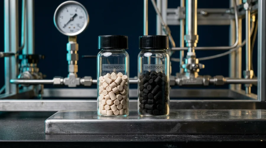
Fouling is the broader term, covering any physical blanketing of the catalyst surface, including polymer films, resinous by-products and solids carried in with the feed. Corrosion products such as rust and scale swept from upstream vessels and pipework can also blind the top of a fixed bed. That is a materials-selection question, addressed in our guide to reactor materials of construction.
In a catalyst limited by pore diffusion, the regime of a large Thiele modulus, observed activity loss depends on where the deposit sits inside the particle. It does not depend only on how many sites the deposit covers, so a carbon analysis alone can mislead. Coke and fouling deposits are usually removable, whereas the next mechanism is not, which is why telling them apart matters before any regeneration is attempted.
Catalyst Sintering and Thermal Degradation: Permanent Loss of Surface Area
Sintering is the loss of active surface area when heat lets metal crystallites grow or a support collapse. Sintering is largely permanent, so it sets the ultimate lifetime of a catalyst regardless of how well poisons and coke are managed. Temperature drives it, and steam accelerates it in many systems. The damage is often done in short excursions — a hot spot, a regeneration burn, a loss of cooling — rather than by steady operation.
Two mechanisms are recognised. In atomic migration, known as Ostwald ripening, atoms detach from small crystallites and re-attach to larger ones. In crystallite migration and coalescence, whole particles move across the support and merge. Both leave fewer, larger crystallites and less exposed metal. Elemental analysis therefore looks unchanged while activity falls, because the metal is still there and simply less of it is accessible.
Two temperature markers, defined in an open-access study of cobalt and nickel catalyst stability, help locate the risk. The Hüttig temperature, about 0.3 of a material's melting point in kelvin, marks the onset of surface-atom mobility. The Tammann temperature, about 0.5 of the melting point in kelvin, marks mobility in the bulk lattice. Nanoscale crystallites melt and sinter at lower temperatures than these bulk figures imply, so they mark a floor for concern, not a safe limit.
The plant consequence follows directly: temperature excursions cost more catalyst life than the average operating temperature suggests. Multipoint thermocouples along the bed record the peak temperature that governs sintering, which a single inlet or outlet reading cannot. Not all catalyst loss involves the catalyst itself, however, and slurry reactors show that most clearly.
Catalyst Attrition and Leaching in Slurry Reactors: When the Catalyst Simply Disappears
In stirred slurry reactors, which dominate batch specialty manufacture, catalyst can vanish without ever losing intrinsic activity. Agitation and pumping grind particles into fines, filters blind or pass those fines, and active metal can dissolve into the liquid. Each route shrinks catalyst inventory, and each looks exactly like deactivation on a conversion plot. Separating loss from true deactivation is therefore the first diagnostic step in any slurry system.
- Attrition — particles fracture or abrade under agitation, pumping and filtration. Laser diffraction particle size distribution (ISO 13320) before and after a run shows fines generation in powder catalysts. ASTM D4058 measures the attrition and abrasion resistance of formed tablets, extrudates and spheres larger than about 1.6 mm.
- Leaching — active metal dissolves from the support into the liquid, the liquid-phase counterpart of vapour compound formation. ICP-MS on the filtered product detects it, and our guide to homogeneous vs heterogeneous catalysis covers it in depth.
- Catalyst loss on filtration and recycle — each filtration, wash or transfer removes a small fraction of the catalyst charge. A metal mass balance across recycles shows whether the loss is physical or chemical.
Once inventory loss is ruled out, the remaining question is which of the three main mechanisms is at work.
Poisoning vs Coking vs Sintering: How to Tell Them Apart
The three dominant mechanisms produce the same headline symptom, falling conversion, but they leave different physical evidence and demand different responses. Treating them as interchangeable is how plants end up burning a catalyst that was poisoned or washing one that was sintered. The table compares causes, reversibility, evidence and remedies side by side. Read it as a diagnostic checklist against a real deactivating reactor, not as independent rows.
| Criterion | Poisoning | Coking / fouling | Sintering |
|---|---|---|---|
| Root cause | Strong chemisorption of impurities on active sites | Carbonaceous or polymeric deposits on the surface and in pores | Crystallite growth or support collapse under heat |
| Typical time course | Abrupt after a bad feed lot, or gradual from trace impurities | Gradual, cumulative with time on stream | Gradual, with steps after temperature excursions |
| Reversibility | Reversible only for weakly bound poisons | Usually reversible by controlled burn-off or washing | Largely permanent |
| Pressure-drop signature | Normally unchanged | Often rising | Normally unchanged |
| Confirming measurement | Poison content of spent catalyst by ICP-MS or XPS | Carbon by thermogravimetric analysis or temperature-programmed oxidation | Metal dispersion by chemisorption; crystallite size by XRD or TEM |
| Primary remedy | Remove the source; guard bed; replace if permanent | Controlled regeneration; adjust hydrogen and temperature | Prevent excursions; replace when area is lost |
Two measurements do most of the work: a carbon analysis and a metal surface area measurement on spent catalyst. High carbon implicates coking. Low carbon with reduced metal area and unchanged metal content implicates sintering, and total surface area by nitrogen adsorption (ASTM D3663, ISO 9277) shows support collapse. If neither fits, look for a poison or a loss mechanism. That triage decides whether regeneration is worth attempting at all, which is the subject of the next section.
Catalyst Regeneration Process: What Can Be Restored and What Cannot
Regeneration restores activity by removing whatever blocks the active sites, so it works only on catalyst deactivation that is physically or chemically reversible. It cannot restore surface area lost to sintering or metal that has left the reactor. Each cycle also carries a cost, because the treatment itself can damage the catalyst. Planning regeneration means knowing both the recovery it delivers and the permanent loss it leaves behind.
Five routes cover most industrial practice:
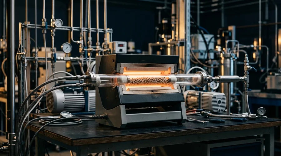
- Controlled coke burn-off — the standard catalyst regeneration process for coke removal, in which air diluted in an inert gas or steam oxidises the deposit to carbon oxides. The oxygen supply is metered because the reaction is exothermic.
- Solvent or hot-liquid washing — removes soluble oligomers and heavy deposits without oxidation.
- Chemical washing — dilute acid or base removes certain deposited contaminants, at some risk to the active phase or support.
- Hydrogen or reductive treatment — reduces oxidised metal surfaces after an oxidative step and converts some carbonaceous deposits to volatile species.
- Redispersion — for some supported noble metals, an oxidising treatment containing chlorine redisperses sintered crystallites, a step used in catalytic reforming but specific to metal and support.
Regeneration is an exotherm problem as much as a chemistry problem. Coke combustion releases heat inside the bed, and in a poorly controlled burn the local temperature rises well above the bulk reading, sintering the catalyst being restored. The physics is the adiabatic temperature rise that governs runaway in a batch reaction, applied to a solid bed; our guide to adiabatic temperature rise and MTSR covers the principle. Regeneration protocols are therefore developed against the measured combustion behaviour of the actual spent catalyst, never borrowed from another system.
A schematic, not data: regeneration (R1, R2) restores most activity, but irreversible loss accumulates, runs shorten, and the charge is replaced once a run ends below the economic minimum.
Spent catalysts are not inert either. Used hydrogenation catalysts such as Raney nickel and palladium on carbon can ignite in air when dry, so unloading and handling need a site-specific hazard assessment.
Knowing which treatments work is only half the decision. The other half is where the treatment happens and whether it is worth doing at all.
In Situ vs Ex Situ Catalyst Regeneration: Regenerate or Replace?
Once regeneration is technically possible, the decision becomes economic and logistical: treat the catalyst in the reactor, send it to a specialist, or replace it. The answer depends on how much activity each cycle recovers, how quickly that recovery decays across cycles, and what downtime and hazard each route brings. Precious-metal catalysts add a further option, because the metal in spent catalyst retains value and specialist refiners can recover it. A sound decision compares cost per tonne of product over the whole campaign, not the price of one treatment.
- In situ regeneration — the shortest downtime, because nothing is unloaded, but treatment conditions are limited to what the reactor and its off-gas system can handle safely.
- Ex situ regeneration — purpose-built equipment controls temperature and atmosphere more tightly, at the cost of unloading, transport, reloading and the handling risk of spent catalyst.
- Replacement — the right call when the loss is permanent or recovery per cycle has decayed. The spent charge still needs safe handling and, for precious metals, carries recoverable value.
Regeneration wins when the loss is reversible and recovery stays high, and replacement wins when it does not. The best decision, however, is the one designed in from the start, which is where reactor configuration and scale-up come in.
Designing for Catalyst Life: Reactor Choice and Lifetime Testing Before Scale-Up
A reactor built as though the catalyst never ages will be the wrong reactor. Catalyst deactivation behaviour should shape configuration from the start, because it decides whether catalyst can be treated or swapped without stopping the plant. Fixed-bed vs slurry catalyst deactivation differs in kind: a fixed bed ages zone by zone, while a slurry ages through inventory loss and decay across recycles. Our guide to batch, semi-batch and continuous reactor selection covers the wider choice, and the three configurations below each handle ageing differently.
- Fixed bed — simple and robust, but the catalyst cannot be treated during a run, so plants accept a shutdown for regeneration or install parallel swing beds. A packed bed behaves much like the plug-flow reactor in our CSTR vs PFR guide: the inlet meets the freshest feed and deactivates first.
- Slurry batch or stirred tank — catalyst recycles from batch to batch with fresh catalyst topped up to hold activity. Inventory turnover becomes a control variable and filtration a critical unit operation.
- Moving-bed and fluidised systems — catalyst circulates continuously between reactor and regenerator. Fluid catalytic cracking, where coke burned in the regenerator also supplies process heat, and moving-bed catalytic reformers with continuous regeneration are the large-scale examples.
Catalyst lifetime testing before scale-up is the step most often omitted. A short screening test on purified reagents with fresh catalyst measures initial activity and says little about production feed lots, coke build-up or attrition over repeated recycles. Extended runs on representative feed, repeated recycle tests and accelerated-ageing protocols expose the mechanism while there is still time to change the route. Scale-down models should therefore include feed variability and time on stream, as our guide to scale-down models sets out. Once a process is running, the same discipline applies to diagnosing it.
Troubleshooting Catalyst Deactivation in a Running Reactor
When conversion falls, the instinct is to change temperature or catalyst before knowing why, and both moves can worsen the underlying problem. A short, ordered diagnosis costs far less than an unplanned change-out. The symptoms below map to the catalyst deactivation mechanisms above and to the first check that separates them. Work through them before committing to regeneration or replacement.
- Catalyst activity dropping over successive batches — in a recycled slurry, run a metal mass balance to separate inventory loss from activity loss. If inventory is intact, compare feed lots for a poison.
- Rising pressure drop across the catalyst bed — points to fouling, coke, fines or corrosion products blocking voids. Inspect the top of the bed and analyse a sample for carbon and for scale-derived metals such as iron.
- Conversion falling while pressure drop holds steady — suggests poisoning or sintering rather than blockage. Sample the bed inlet and outlet and compare poison content and metal dispersion.
- Selectivity loss as the catalyst ages — partial poisoning, coke deposition and sintering can each change the product distribution. Trend by-product ratios alongside conversion, because selectivity and activity do not always deteriorate together.
- Hot spots in the catalyst bed during regeneration — the burn is releasing heat faster than the bed can remove it. Review the protocol against measured combustion data before the next cycle.
- Activity that does not recover after regeneration — points to a permanent mechanism, or to damage from the treatment itself. Characterise the regenerated catalyst before another cycle.
Most of these checks use analyses a laboratory already runs. What they need is the discipline to sample the catalyst before changing conditions.
A Decision Framework for Managing Catalyst Deactivation
Catalyst life is managed, not endured. Teams that keep it long treat catalyst deactivation as a design input in route selection, a monitored variable in operation and a costed line in the business case. The sequence below turns the earlier sections into decisions in the order they arise. It works for a new process and for an existing one that keeps losing catalyst earlier than budgeted.
- Identify the mechanism first — characterise spent catalyst for carbon, poison content, metal surface area and crystallite size before choosing a remedy.
- Fix the source of poisons — specify and test incoming feed, and add a guard bed or purification step where the poison cannot be excluded at source.
- Watch the temperature you cannot see — instrument the bed with multiple thermocouples and log peak temperature, because excursions drive sintering.
- Treat regeneration as a designed step — qualify it against measured combustion behaviour, and confirm both the recovery per cycle and the permanent loss it leaves.
- Test life, not just activity — run extended and recycle tests on production-representative feed before committing to scale.
- Cost the whole campaign — compare regeneration, replacement and metal recovery on cost per tonne of product over the full run.
We work through this sequence with manufacturers choosing a catalyst route, planning a scale-up, or trying to understand why a running process loses catalyst early. Our process consulting practice provides chemical process development services, including route selection and catalyst-life assessment as a reaction engineering consultant would. Our scale-up support service, as a scale-up partner, extends that into pilot plant support and technology transfer. The aim of the contract process development work is a process that holds its catalyst charge for the campaign length the business case assumes.
Frequently Asked Questions
What causes catalyst deactivation?
Catalyst deactivation has six recognised causes. Poisoning is strong binding of impurities to active sites, and fouling and coking are deposits that block sites and pores. Thermal degradation and sintering shrink the active surface. The other three are vapour compound formation, solid-state reactions that form an inactive compound, and attrition and crushing.
In liquid-phase processes, leaching of active metal adds a further route. Which mechanism dominates depends on feed purity, temperature, catalyst formulation and reactor type, so the cause must come from analysis of the spent catalyst rather than assumption.
What is catalyst poisoning, and how does it differ from coking?
Catalyst poisoning is the loss of activity when an impurity chemisorbs strongly on active sites and blocks them, as sulfur compounds do on nickel, palladium and platinum. Coking is different: carbon-rich deposits build up from the reaction itself, covering sites and blocking pores. Poisoning is fixed by removing the impurity source, while coking is usually treated by burning off or washing out the deposit. A carbon analysis of the spent catalyst separates the two.
What is the difference between reversible and irreversible catalyst deactivation?
Reversible deactivation can be undone by a treatment that removes the cause, and irreversible deactivation cannot. Coke, soluble fouling deposits and weakly bound poisons are typically reversible, whereas sintering, strongly bound poisons and loss of active metal are typically irreversible. The boundary is imperfect, because repeated regeneration itself causes some permanent loss. That is why each restored activity peak sits lower than the last, and why every catalyst is eventually replaced.
Can a deactivated catalyst be regenerated?
Often yes, provided the deactivation is reversible. Coked catalysts are commonly regenerated by controlled burn-off with dilute oxygen, fouled catalysts by solvent washing, and some noble-metal catalysts by an oxidising treatment that redisperses sintered metal. Regeneration cannot restore surface area lost to sintering or metal that has left the reactor. Coke combustion also releases heat in the bed, so the protocol must be developed against the measured combustion behaviour of the actual spent catalyst.
How do you tell which deactivation mechanism is occurring?
Start with plant data, then confirm on spent catalyst. Rising pressure drop points to fouling, coke, fines or scale. A front of lost activity advancing from the bed inlet points to a feed poison, and loss that follows the hottest zone points to sintering.
Then measure carbon by thermogravimetric analysis or temperature-programmed oxidation, poisons and leached metal by ICP-MS, and metal surface area by chemisorption. Crystallite size comes from X-ray diffraction or electron microscopy, and total surface area from nitrogen adsorption (ASTM D3663).
How long does an industrial catalyst last?
There is no single figure, because lifetime is set by the mechanism and the process. Argyle and Bartholomew's review contrasts fluid catalytic cracking catalyst, which loses activity over seconds and is regenerated continuously, with iron ammonia synthesis catalyst, which can last five to ten years.
Specialty processes sit between these extremes. A recycled slurry catalyst is replaced after a batch count set by its measured loss rate. A fixed-bed catalyst is judged by campaign length between regenerations, and extended tests on production-representative feed give a defensible estimate for a specific process.
Losing Catalyst Faster Than Your Business Case Assumes?
Global Formulation provides route selection, process development and scale-up partnership — catalyst-life assessment, regeneration strategy and pilot-scale validation, so a route holds its performance beyond the first campaign.
Talk to Our Process Team