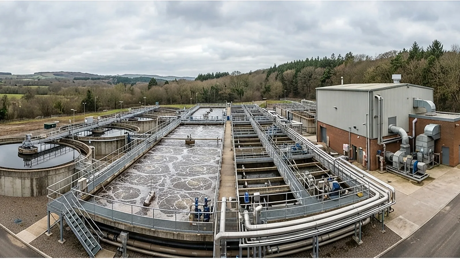
ETP Treatment Train
The stages a treatment plant is built from, and where each one earns its place.
Design
ETP Unit Processes
The unit processes used in industrial effluent treatment, what each one removes, and the design basis we check before selecting it.
Equalisation and neutralisation
PretreatmentpH correction system
Scope & Configuration
Buffer volume and mixing that smooth flow and load before treatment.
Method & Approach
Size retention from the measured discharge pattern, provide mixing (and aeration if the stream can go septic), and stage pH correction with a reagent chosen for cost and sludge impact.
Screening, grit and oil separation
PretreatmentGrit removal
Oil–water separators
Scope & Configuration
Removal of coarse solids and free oil before downstream units.
Method & Approach
Select screens and separators to the solids and free-oil load, and size them for peak flow.
Coagulation, flocculation and clarification
Physico-chemicalFlocculation and clarifier design
Scope & Configuration
Destabilise and aggregate fine particles, then settle or float the flocs.
Method & Approach
Choose coagulant and polymer by jar testing, size flash mixing, flocculation and the clarifier to the overflow rate, and match dosing to flow.
Dissolved air flotation
Physico-chemicalScope & Configuration
Micro-bubbles lift light solids and oils to the surface for skimming.
Method & Approach
Size the unit to the hydraulic and solids loading, set the air saturation system, and pair it with chemical conditioning.
Aerobic biological treatment
BiologicalBlower and diffuser selection
Scope & Configuration
Activated sludge, moving-bed biofilm or sequencing-batch processes that oxidise organics.
Method & Approach
Select the process on load variability and footprint, size volume from organic load and sludge age, and size aeration from oxygen demand.
Anaerobic treatment
BiologicalBiogas handling
Scope & Configuration
Anaerobic reactors that convert high organic loads to biogas before aerobic polishing.
Method & Approach
Size the reactor on volumetric COD loading, protect it from toxic and sulphate-rich streams, and arrange biogas collection with safe use or flaring.
Advanced oxidation and polishing
Advanced & reuseCarbon and filter polishing
Scope & Configuration
Oxidants, ozone or UV-based treatment and adsorption for what biology cannot remove.
Method & Approach
Test oxidant and carbon options at bench scale, size contact time or bed volume from the results, and place the step where it treats the smallest, most concentrated stream.
Membranes, evaporation and ZLD
Advanced & reuseConcentrate and salt plan
Scope & Configuration
Membrane concentration, then evaporation and crystallisation to recover water and isolate solids.
Method & Approach
Select membranes to the water quality, maximise recovery before evaporation, and choose the evaporator type on energy cost.
Sludge thickening and dewatering
SludgeSludge handling layout
Scope & Configuration
Reduce sludge volume and prepare it for disposal or reuse.
Method & Approach
Match thickening and dewatering equipment to sludge type and quantity, and plan storage, conveying and conditioning.
How an ETP project runs
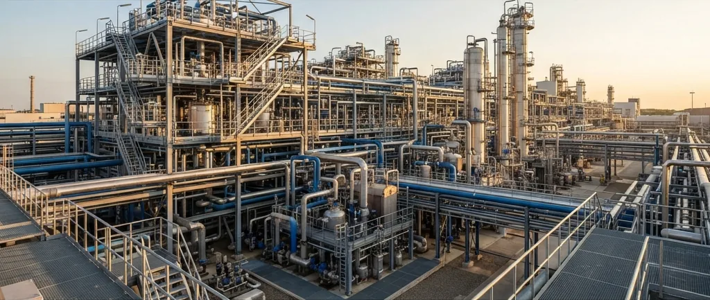
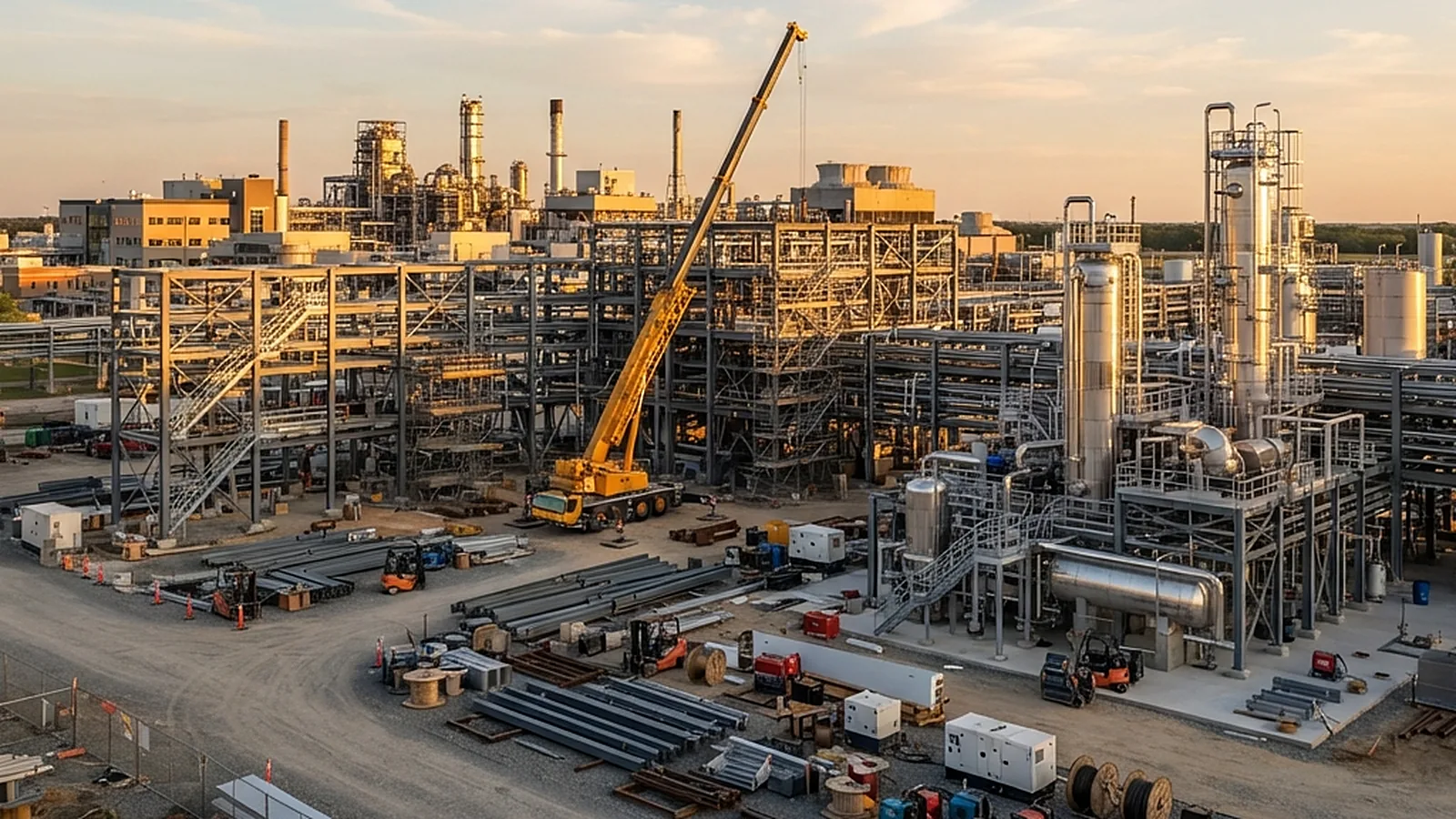
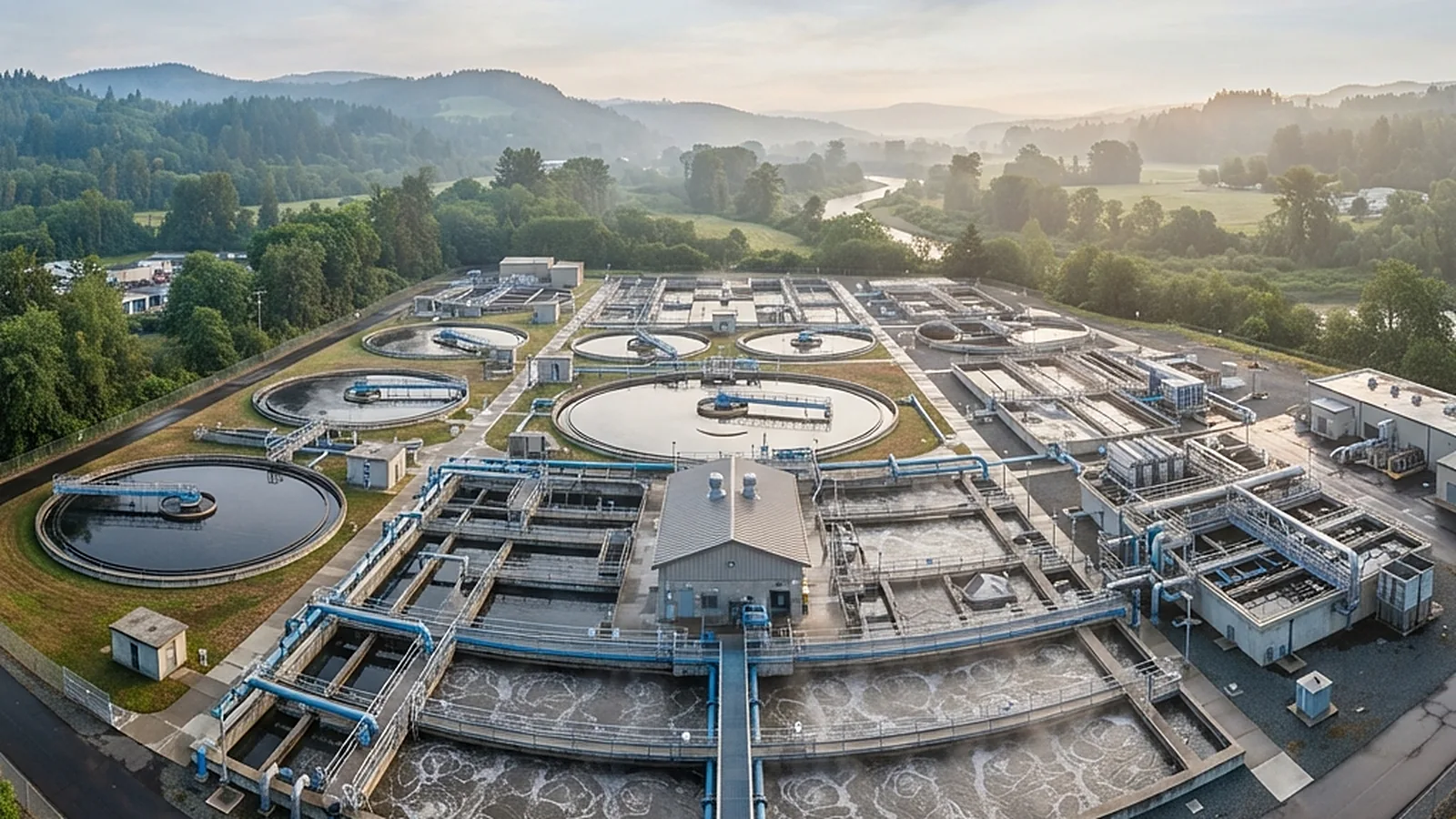
From Raw Effluent to Treated Water
Each stage fixes decisions that the next stage depends on, from stream data to a plant that meets its limits.
Stream Survey & Characterisation
Sample and analyse each stream, record flow patterns over the day and between batches, and identify what must be kept separate.
Speak With Our Engineers Treatability Testing
Run bench tests on the real effluent to confirm which treatment steps work and what dose or loading each one needs.
Speak With Our Engineers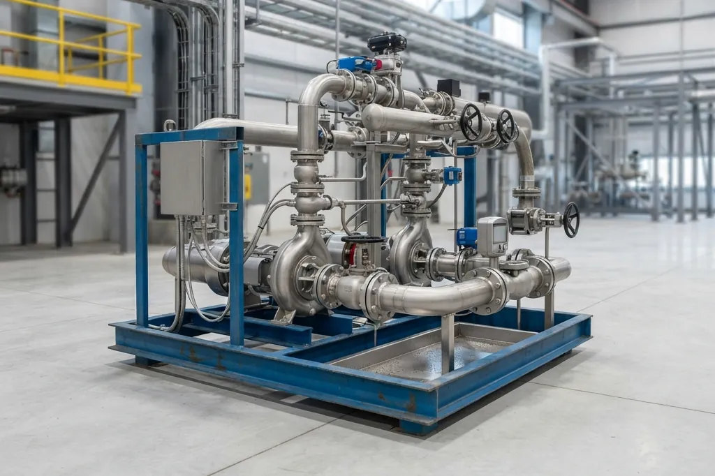
Process Design & Sizing
Prepare the mass balance, hydraulic profile and unit sizing, with PFDs and P&IDs and a defined operating philosophy.
Speak With Our Engineers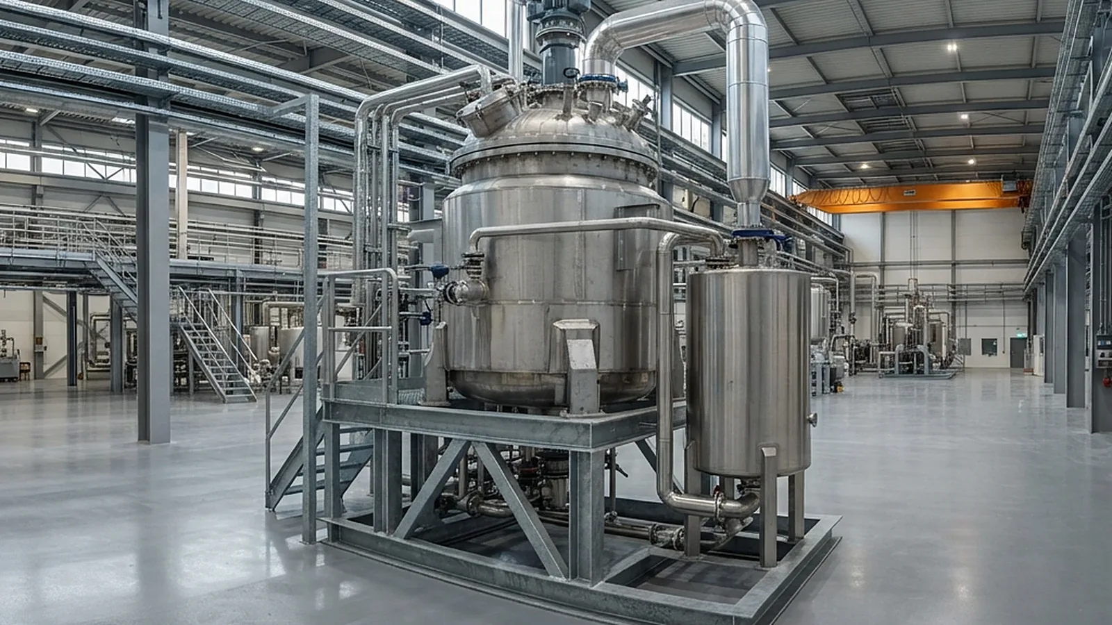
Layout, Utilities & Safety Review
Develop the plant layout and utilities, and review hazards such as chemical storage and biogas, with a HAZOP where the risk warrants it.
Speak With Our Engineers Procurement & Construction Support
Issue equipment specifications, compare vendor offers, and support installation and inspection against the drawings.
Speak With Our Engineers Start-Up & Performance Verification
Support seeding and ramp-up, verify performance against the design basis, and hand over operating procedures and operator training.
Speak With Our EngineersNeed an effluent treatment plant designed or upgraded?
Share the process, the flows and the discharge or reuse requirement, and we will outline the characterisation and design work needed.
Discuss Your ETP ProjectEffluent & Water Treatment Knowledge Base
Coagulation, flocculation, membrane and treatment-chemistry guides from our technical team.
Polyaluminium Chloride Coagulant: Basicity and Dosing
Polyaluminium chloride coagulant explained: basicity, Al13 chemistry, PAC vs alum, jar-test dosing, residual aluminium limits, IS 15573 and EN 17034.
Read MoreCoagulant Selection in Water Treatment: Alum, Ferric, PAC
Read MorePolyelectrolyte Flocculant Selection: Anionic vs Cationic
Read MoreRO Membrane Cleaning Chemicals: Acid, Alkaline and CIP
Read MoreReverse Osmosis Pretreatment: SDI, Dechlorination, Filters
Read MoreFrequently asked questions
Straight answers to the questions we hear most often.
What information is needed to design an effluent treatment plant?
The design needs measured flow (average and peak), the composition of each stream, how the discharge varies over the day and between batches, the discharge or reuse limits that apply, and the land and utilities available. Where measurements do not exist, a sampling programme comes first.
Why should effluent streams be segregated?
Mixing a concentrated, toxic or high-salinity stream into the main flow can inhibit biological treatment and enlarge every downstream unit. Handling the small concentrated stream separately is usually cheaper than treating the whole flow to the same standard.
What is the difference between BOD and COD, and why do both matter?
BOD measures the oxygen consumed by microorganisms breaking down organic matter over a set period, while COD measures the oxygen needed to chemically oxidise nearly all of the organic matter. The ratio of the two indicates how much of the load is biodegradable, which helps judge whether biological treatment is suitable.
When is biological treatment not enough?
When the effluent contains organics that microorganisms cannot degrade, strong colour, or compounds that are toxic to the biomass, biological treatment alone will not meet the limit. Pretreatment, advanced oxidation, adsorption or membranes are added where the characterisation shows they are needed.
What are the options for sludge from an effluent treatment plant?
Sludge is thickened and dewatered to reduce its volume, then sent for disposal, treatment or beneficial use depending on its classification. Whether it is hazardous depends on the process and on local rules, which is why the sludge route is decided during process design.
Can you upgrade or debottleneck an existing effluent treatment plant?
Yes. An upgrade starts with a review of how the plant performs against its design basis, and usually leads to targeted changes such as segregation, equalisation, aeration or polishing rather than a full rebuild.
Related engineering services
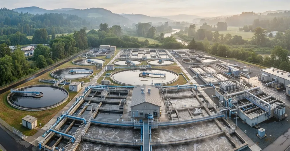
Water & Wastewater Engineering
Water audits, treatment systems, effluent plants, dosing and control, zero liquid discharge and reuse for process industries.
Explore the service →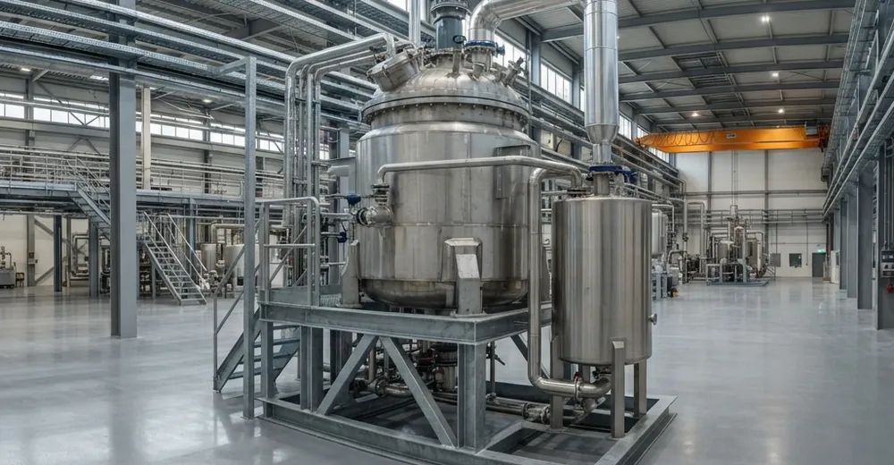
Process Safety & Thermal Hazard Assessment
Reaction calorimetry, runaway analysis, HAZOP, LOPA and relief sizing, so hazards are designed out before construction.
Explore the service →
EPC / EPCM & Project Management
Feasibility, FEED, detailed engineering, procurement, construction management and commissioning for process plants.
Explore the service →Reach us directly.
Prefer a direct line? Reach our formulation team through any channel below — we typically respond within one business day.