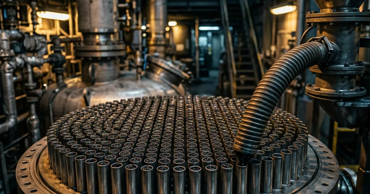
A catalyst that performs well in a bench reactor can fail in the plant for reasons the catalyst never caused. The bed runs hot near the inlet, the pressure drop climbs past what the compressor can deliver, or part of the flow bypasses the catalyst along the wall. Fixed bed reactor design decides whether the rate you measured survives scale-up, and it sets catalyst life, selectivity and the length of each production campaign. This guide shows how to size the catalyst bed and trade particle size against pressure drop with the Ergun equation. It then covers heat management in adiabatic and multitubular beds and the move from a pilot tube to a plant. The article sits within our chemical reaction engineering practice and builds on our guides to CSTR vs PFR reactor selection and catalyst deactivation and regeneration.
What Is a Fixed Bed Reactor? The Design Decisions Behind a Packed Catalyst Bed
A fixed bed reactor holds solid catalyst particles stationary in a vessel while the reacting fluid flows through the gaps between them. The equipment is also called a packed bed reactor, so packed bed reactor design and fixed bed reactor design are the same discipline. Its appeal is simple: the catalyst never leaves the reactor, so no filter or centrifuge has to separate it from the product. The price is that particle, bed depth, flow pattern and heat removal all act on one bed at the same time.
The Wikipedia entry on packed beds, citing Fogler’s textbook, lists high conversion per unit mass of catalyst, relatively low operating cost and continuous operation as the advantages. Thermal gradients, poor temperature control and difficult servicing are the stated disadvantages. Each disadvantage turns into a design task in the sections below. Eigenberger’s Fixed-Bed Reactors chapter in Ullmann’s Encyclopedia of Industrial Chemistry is the place to go for further configurations.
| Design decision | What it controls | Plant consequence when it is wrong |
|---|---|---|
| Catalyst volume and space velocity | Conversion and the interval between catalyst changes | Missed conversion from day one, or an early forced shutdown as the catalyst ages |
| Particle size and shape | Pressure drop and internal diffusion (the effectiveness factor) | High compression cost, or expensive catalyst that sits idle inside the pellet |
| Bed depth and tube diameter | Residence-time distribution, wall effects and heat removal | Wall bypassing, poor conversion and local overheating |
| Heat-removal scheme | Peak bed temperature, selectivity and catalyst life | Hot spots, sintering, coking or runaway |
| Flow distribution and catalyst loading | How evenly every part of the bed is used | Channelling, and a few overworked tubes or zones |
| Mechanical design and materials | Pressure rating, tube-sheet integrity and corrosion allowance | Leaks, unplanned shutdowns and costly re-tubing |
The working model behind fixed bed catalytic reactor design is a plug flow reactor with the rate expressed per unit mass of catalyst, and it feeds all six decisions. Our guide to CSTR vs PFR reactor selection explains why plug flow needs less volume than a stirred tank for most positive-order reactions. Real beds depart from plug flow through wall effects, channelling and axial mixing, and each departure is a design topic below. The model’s first output is the amount of catalyst, so sizing comes next.
Fixed Bed Reactor Design Starts with Catalyst Volume: Space Velocity and the Plug-Flow Equation
Catalyst volume is the first number in fixed bed reactor design, and every later choice inherits its error. A bed that is too small misses conversion from the first day. A bed that is too large ties up expensive catalyst and lengthens every heat-up, reduction and regeneration cycle. Fixed bed reactor sizing therefore starts from the plug-flow design equation, which converts a measured rate into a bed volume.
For plug flow, the catalyst mass (W) needed for a conversion (X) is W = FA0 ∫ dX / (−r′A). The integral runs from zero to X. Here FA0 is the molar feed rate of the key reactant, and −r′A is its consumption rate per unit mass of catalyst. This is the standard packed bed design equation found in textbooks such as Fogler’s Elements of Chemical Reaction Engineering. For a first-order reaction at constant volumetric flow (v0) it reduces to W = (v0/k′) ln[1/(1 − X)], where k′ is the rate constant per unit mass of catalyst.
The logarithm carries the plant consequence. For a first-order reaction, moving from 90% to 99% conversion raises ln[1/(1 − X)] from 2.30 to 4.61, so the same flow and rate constant need twice the bed. Reaching 99.9% needs three times the 90% bed (6.91 against 2.30). A tight conversion specification is therefore a catalyst-volume decision long before it is a separation decision.
Beds are specified in space velocity, the feed rate per unit of catalyst. Its reciprocal is the space time, the nominal residence time in the bed, and the Wikipedia residence time entry gives space time as the chemical-engineering name for that ratio. Three bases are in common use, and the table shows what each one measures.
| Basis | Definition | Typical use | Watch-out |
|---|---|---|---|
| LHSV | Liquid volumetric feed rate per unit volume of catalyst bed (h−1) | Liquid-phase and trickle bed reactions such as hydrotreating | Quote the liquid temperature, because liquid volume changes with it |
| WHSV | Mass feed rate per unit mass of catalyst (h−1) | Comparing catalysts on a mass basis | Bed volume still depends on the loaded bulk density |
| GHSV | Gas volumetric feed rate at stated reference conditions per unit volume of catalyst bed (h−1) | Gas-phase reactions | Two GHSV values compare only when the reference conditions match |
Volume fixes how much catalyst the reactor holds. Particle size decides how much of that catalyst works and how hard the fluid is pushed through it.
Catalyst Particle Size Selection and Pressure Drop: The Ergun Equation Trade-Off
Particle size is the main lever in a fixed bed, and it pulls in two directions. Smaller particles shorten the diffusion path inside each pellet, so more of the catalyst does useful work. They also pack more tightly, so the fluid loses more pressure crossing the bed. The Thiele modulus describes the first effect and the Ergun equation describes the second.
How Do You Calculate Pressure Drop in a Packed Bed? The Ergun Equation
Pressure drop sets compressor or pump duty and, in a multitubular reactor, the flow each tube receives. Sabri Ergun’s 1952 equation predicts it from fluid properties, particle size and void fraction. It adds a viscous term that dominates at low velocity and an inertial term that dominates at high velocity. Both terms rise as particle size falls, the viscous term faster than the inertial one.
The Wikipedia Ergun equation page gives Δp = 150 μ L (1 − ε)2 u / (dp2 ε3) + 1.75 L ρ (1 − ε) u2 / (dp ε3). Here Δp is the pressure drop across the bed, μ the dynamic viscosity, ρ the fluid density, L the bed length and ε the void fraction. The superficial velocity u is the velocity the fluid would have in the empty tube at the same volumetric flow. The particle diameter dp is the equivalent spherical diameter for shaped pellets.
Two features drive design. The inertial term grows with the square of velocity, so a gas stream with high mass flux pays heavily for speed. Void fraction enters through ε3 in the denominator of both terms, so a few percentage points of extra packing density cost a disproportionate pressure drop. That is why the loading method matters, as a later section shows.
Thiele Modulus and Effectiveness Factor: What a Smaller Particle Buys
The effectiveness factor tells you what fraction of the catalyst’s intrinsic rate the pellet actually delivers. Inside a porous pellet the reactant must diffuse to the active sites while it reacts, so the interior works at lower concentration than the surface. Ernest Thiele introduced the modulus that captures this balance in his 1939 paper on the relation between catalytic activity and size of particle. A high Thiele modulus (φ) means reaction outruns diffusion, and only the outer shell of the pellet contributes.
For a first-order reaction in slab geometry the effectiveness factor is η = tanh φ / φ, as the Wikipedia Thiele modulus entry gives it. The modulus scales with the characteristic length of the pellet, so a smaller pellet lowers φ and raises η. The table combines this with the Ergun equation for one assumed system, to show both sides of the trade.
| Particle diameter (mm) | Assumed Thiele modulus φ | Effectiveness factor η | Relative output per bed volume | Δp, liquid case (kPa) | Δp, gas case (kPa) |
|---|---|---|---|---|---|
| 6.0 | 3.0 | 0.33 | 1.0 | 1.4 | 11.0 |
| 3.0 | 1.5 | 0.60 | 1.8 | 4.1 | 23.3 |
| 1.5 | 0.75 | 0.85 | 2.6 | 13.9 | 52.3 |
Illustrative arithmetic, not measured data. Both cases use a void fraction of 0.40 and a bed length of 3 m. Liquid: density 800 kg/m3, viscosity 1 mPa·s, superficial velocity 0.01 m/s. Gas: density 5 kg/m3, viscosity 0.02 mPa·s, superficial velocity 0.5 m/s. The Thiele modulus is assumed to be 3.0 at 6 mm and proportional to particle diameter.
In this example, halving the diameter from 6 mm to 3 mm lifts output per bed volume by 1.8 times, because the effectiveness factor rises from 0.33 to 0.60. The liquid-case pressure drop rises threefold and the gas-case pressure drop more than doubles. Going on to 1.5 mm gains only another 40% in output (2.6 against 1.8), while the liquid pressure drop climbs again to 13.9 kPa. The best size sits where the next halving buys less output than it costs in compression, pumping and mechanical rating.
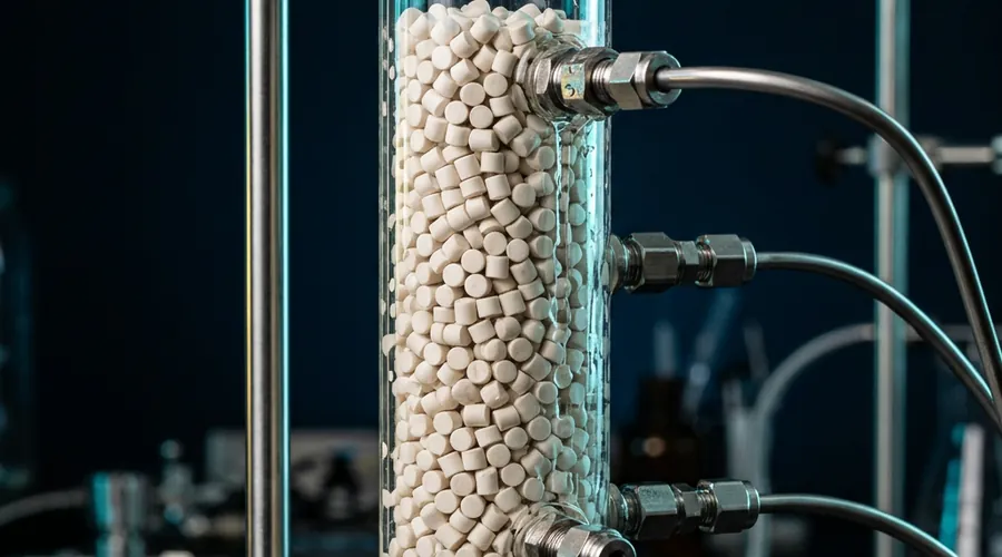
Shape offers a second route. Hollow and spoked shapes combine a high surface-area-to-volume ratio with low pressure drop. The Wikipedia steam reforming entry lists spoked wheels, gear wheels and rings with holes as shapes for the nickel catalyst in multitubular packed bed reactor tubes inside a furnace.
Bench and plant often differ here. Kinetic tests are usually run on small particles to keep internal diffusion out of the data, while a plant bed uses larger pellets to hold the pressure drop down. The two have different effectiveness factors, so the bench rate overstates the plant rate unless the correction is made. Particle size is settled, and the next question is how the tube or vessel diameter and the loading method shape the flow.
Bed Geometry, Wall Effects and Flow Distribution in Packed Beds
Flow distribution in packed beds decides whether every particle sees the same feed or a few see most of it. Near a tube wall the particles pack less tightly than in the interior, so fluid takes the easier path along the wall. Kwapinski and co-workers describe a wall region that extends about half a particle diameter from the wall, with higher voidage and higher velocity. The narrower the tube relative to the particle, the larger the share of flow that bypasses the core.
Published guidance on the minimum tube-to-particle diameter ratio is not a single number. A pilot-plant kinetics thesis from North-West University surveys the literature. It reports that Smith found deviations from plug flow insignificant above a ratio of 30, and that Whitaker suggested a ratio above 10 for neglecting radial transport effects. It also reports a lower limit of 4 set by Vortmeyer and Winter for continuum reactor models to hold. Treat the spread as a warning that a small-diameter pilot tube needs a wall-effect check.
Why Every Tube in a Multitubular Reactor Needs the Same Pressure Drop
A multitubular reactor is thousands of parallel fixed beds fed from one inlet. Take an assumed 20 m3 catalyst charge in tubes of 25 mm internal diameter and 6 m length. Each tube holds 0.00295 m3, so the charge fills about 6,800 tubes. All of them see the same inlet and outlet pressure, so any tube that packs more tightly receives less flow.
Suppose one tube has 5% more resistance than its neighbours. Pressure drop varies with velocity to a power between one and two, so its flow falls by about 2.4% in fully inertial flow and 4.8% in fully viscous flow. The low-flow tube carries less fluid to absorb the reaction heat, so for an exothermic reaction it runs hotter. The Fluor Daniel article on filling fixed bed tubular reactors calls close pressure-drop values across tubes essential. It gives ±5% of a reference tube as good practice, with the reference found by passing the equivalent gas flow through one tube.
The same article describes a layer of inert material on a supporting screen above the tube sheet, which spreads the feed evenly to every tube. Large adiabatic converters attack the pressure drop differently. The Wikipedia Haber process entry describes an ammonia converter with three radial flow catalyst beds, which reduces pressure drop compared with axial flow.
Dense Loading vs Sock Loading
Loading method sets the void fraction of the bed, and void fraction enters the Ergun equation through its cube. Dense loading uses a device to spread the catalyst evenly in the reactor. It reduces void space and channelling and raises catalyst density. Sock loading is the least expensive method, and Chemical Engineering magazine’s guide to solid catalyst loading describes both.
The trade is cost and care against density and uniformity. Dense loading needs constant attention to the feed rate and normally puts an operator inside the reactor, so the work belongs in a confined-space entry plan. The same guide links proper loading to better flow distribution and to preventing settling of the bed. Whichever method is chosen, measure the pressure drop after loading and compare it with the design value before the first feed. Even flow is only half of the job, because the bed must also lose heat evenly.
Heat Management in Fixed Beds: Adiabatic Stages, Quench and Multitubular Cooling
Fixed bed reactor heat transfer is poor by nature, which is why heat management usually decides the reactor type. The bed has no stirrer to even out temperature, so thermal gradients persist along and across it. Two strategies result. Either the bed runs adiabatically and the process stream carries the heat out, or the heat passes through tube walls to a circulating fluid.
Adiabatic Fixed Bed Reactor Design with Interstage Cooling
In an adiabatic bed no heat leaves through the wall, so the stream temperature changes in proportion to conversion. The adiabatic temperature rise (ΔTad) is the rise the stream would show at full conversion with no heat removal. The rise across the bed equals ΔTad multiplied by the conversion reached, when the heat capacity of the stream stays constant. If the catalyst or the selectivity tolerates only part of that rise, conversion per bed is capped.
Take an assumed ΔTad of 150 K and a catalyst that tolerates a 50 K rise per bed. Each bed can then convert one third of the feed, so full conversion needs three beds with cooling between them. Equilibrium-limited exothermic reactions add a second reason for interstage cooling. Equilibrium conversion falls as temperature rises, so cooling between beds restores the driving force.
Two kinds of hardware deliver the cooling. The Wikipedia Haber process entry describes both for ammonia converters. One design injects cold gas between about ten catalyst fills, and its stated drawback is incomplete conversion of the cold gas in the last bed. The other cools the reaction mixture between three catalyst beds with heat exchangers, and the entry credits it with better temperature control and better conversion than cold-gas injection. The Wikipedia contact process entry likewise describes the sulfur dioxide converter as usually a tower with multiple catalyst beds.
Our guide to adiabatic temperature rise and MTSR explains how ΔTad follows from the measured heat of reaction and heat capacity. It also shows why that number sets the thermal-safety case for the bed.
Multitubular Fixed Bed Reactor Design: Heat Through the Tube Wall
When the heat of reaction is too large for adiabatic stages, the catalyst goes inside tubes and a heat-transfer fluid circulates outside them. The reactor then resembles a shell-and-tube heat exchanger. The Wikipedia chemical reactor entry notes that tubular reactors can be designed like heat exchangers for strongly exothermic reactions and like furnaces for strongly endothermic ones. Both layouts appear in industry.
Tube diameter is the main heat-removal variable. The heat-transfer area per unit of bed volume in a cylindrical tube is 4/D. Halving the bore therefore doubles the area per unit of catalyst: 160 m2/m3 for a 25 mm tube against 80 m2/m3 for a 50 mm tube. Smaller tubes cost more tubes, more tube-sheet area and tighter pressure-drop matching. They also lower the tube-to-particle diameter ratio, which brings the wall effects back. Three industrial cases show the range of fixed bed practice, from cooled tubes to fired tubes to a vapour-phase specialty hydrogenation.
- Fischer–Tropsch synthesis — the Wikipedia Fischer–Tropsch entry describes a multitubular fixed-bed reactor with small-diameter catalyst tubes surrounded by cooling water, and an upper-temperature limit of 257 °C. Excess temperature leads to carbon deposition and blockage.
- Steam reforming — the endothermic case. The reaction tubes sit inside the combustion chamber of an industrial furnace, which supplies the heat.
- Fatty alcohol manufacture — the background of US patent 5,124,491 states that the predominant quantity of native fatty alcohols was then made from distilled fatty acid methyl esters. The esters pass in the vapour phase, with a large excess of hydrogen, over a fixed bed of copper-containing mixed oxide catalysts such as copper chromite spinel. The catalysts are used as particles or extrudates. Fatty alcohols are a surfactant intermediate, which connects this reactor choice to our surfactants practice.
A multitubular reactor is built like a heat exchanger, so its shell, tube sheets and heads follow codes such as ASME BPVC Section VIII and the TEMA standards. Our guide to reactor materials of construction covers how the service sets the metallurgy. The next section turns the two heat-removal schemes into a selection decision.
Adiabatic vs Multitubular Fixed Bed Reactor: Choosing the Heat-Removal Scheme
The adiabatic vs multitubular fixed bed reactor decision is mainly a heat-balance decision made early, because it fixes the vessel type, the loading task and the scale-up route. Strongly exothermic reactions with temperature-sensitive selectivity favour tubes. Moderate exotherms favour simple adiabatic beds. Capital cost, catalyst inventory and ease of loading push the other way, and the table sets the two side by side.
| Criterion | Adiabatic bed (single or staged) | Multitubular bed |
|---|---|---|
| Heat removal | Carried by the process stream; quench or exchangers between beds | Through tube walls to a circulating heat-transfer fluid |
| Temperature profile | Rises with conversion within each bed | Held nearer the coolant temperature, with an axial peak and a radial gradient |
| Suits | Moderate ΔTad, or equilibrium-limited reactions cooled between stages | Strongly exothermic or endothermic reactions with temperature-sensitive selectivity |
| Loading task | One bed or a few | Thousands of tubes, each matched in pressure drop |
| Pressure drop | Set by bed depth and diameter; radial flow lowers it | Set by tube length; every tube must match |
| Scale-up route | Widen the vessel at the same bed depth | Add tubes of the same diameter and length |
| Industrial examples | Ammonia converters; multi-bed sulfur dioxide converters | Fischer–Tropsch fixed-bed reactors; steam reforming tubes |
Three questions settle most cases. Is ΔTad small enough to stay inside the catalyst limit across one or a few beds? Does selectivity depend on holding temperature within a narrow band? Can the plant manage the loading task at the tube count that the heat duty requires? Gas–liquid systems add a flow-regime problem that neither scheme addresses, and the next section covers it.
Trickle Bed Reactor vs Packed Bed Reactor: What Changes When a Liquid Flows Through the Bed
A trickle bed reactor is a fixed bed in which a liquid and a gas flow through the catalyst together. The difference from a single-phase packed bed is the second phase, which must wet the catalyst and spread evenly across the bed. The Wikipedia trickle-bed reactor entry defines it as downward liquid flow with co-current or counter-current gas over a packed bed of catalyst particles. It calls the design the simplest reactor type for catalytic reactions where gas and liquid are both present, with liquid-phase hydrogenation, hydrodesulfurisation and hydrodenitrogenation among its typical uses.
| Feature | Single-phase packed bed | Trickle bed |
|---|---|---|
| Phases in the bed | One fluid phase, gas or liquid | Gas and liquid together over the solid |
| Main distribution problem | Bypassing, channelling and wall effects | Liquid distribution and catalyst wetting |
| Extra mass-transfer step | None between fluid phases | Gas must dissolve in the liquid before reaching the catalyst |
| Typical service | Gas-phase converters such as ammonia synthesis | Hydrotreating and liquid-phase hydrogenation |
The hydrodynamics are the hard part. The same entry says the reactor is simple but its hydrodynamics are extremely complex, and it points to Satterfield’s 1975 AIChE Journal review of trickle-bed reactors as the classic introduction. Liquid maldistribution is a measured problem: an electrical resistance tomography study of liquid spread and maldistribution in the trickle bed reactor examines it directly. Wetting and liquid spread depend on the liquid and gas mass velocities, so a pilot tube for a trickle bed should run the same velocities as the plant. The next section places the whole fixed bed family beside its main alternatives.
Fixed Bed vs Fluidised Bed vs Slurry Reactor for Solid-Catalysed Reactions
A fixed bed vs fluidised bed reactor choice is a choice between simplicity and temperature uniformity. A fixed bed vs slurry reactor choice is a choice between having no catalyst separation step and having a stirred, well-mixed liquid. Each option fixes the catalyst particle size, the downstream separation and the way the plant handles spent catalyst. Our guide to homogeneous vs heterogeneous catalysis frames the wider catalyst question, and the table here compares the three reactor types.
| Feature | Fixed bed | Fluidised bed | Slurry reactor |
|---|---|---|---|
| Catalyst form | Millimetre-scale shaped pellets or extrudates | Granular particles suspended by the fluid | Fine powder suspended in liquid |
| Temperature uniformity | Gradients along and across the bed | Uniform mixing and temperature, compared with packed beds | Well-mixed liquid |
| Catalyst–product separation | None needed | Entrained particles must be retained | Filtration or settling after the reactor |
| Main design risk | Hot spots and maldistribution | Entrainment, wear of internal surfaces and bed collapse on loss of flow | Attrition, leaching and filtration load |
| Size and energy | Relatively low operating cost | Often larger and more energy-intensive than other designs | Stirring power plus a filter |
| Usual fit | Dedicated continuous lines with long catalyst life | Large throughput where uniform temperature is essential | Batch or campaign production where products change often |
Fluidised bed entries follow the Wikipedia fluidized bed reactor entry. Fixed bed entries follow the packed bed entry cited above, and slurry entries follow our guide to catalyst deactivation and regeneration.
For specialty chemicals the deciding factors are usually volume per product and catalyst life. A dedicated continuous line justifies a fixed bed when the catalyst survives long enough between changes. Where several products share one reactor and the catalyst is consumed or leached, a slurry route avoids a dedicated bed. Our guide to batch, semi-batch and continuous reactor selection sets out the wider logic. The comparison also shows where fixed beds fail, which is the subject of the next section.
Troubleshooting Fixed Bed Reactors: Hot Spots, Channelling and Rising Pressure Drop
Fixed bed failures leave signatures in the temperature and pressure data, and most trace back to one of three design variables. The symptom names the variable: heat, flow distribution or catalyst condition. Reading the signature first saves a long and expensive search through catalyst changes. The sections below separate the symptoms, and the list that follows pairs each with its usual cause.
Why Do Fixed Bed Reactors Have Hot Spots?
A hot spot forms where heat release outruns heat removal. In an exothermic fixed bed the reactant concentration, and therefore the rate, is highest near the inlet, so heat release peaks there before conversion consumes the reactant. The Fluor Daniel article reports that, with uniform catalyst concentration, the hot spot starts near the top and moves downward as the catalyst loses activity.
Diluting the catalyst with inert material, in a pattern that varies with reactor height, is the common way to flatten the profile, as that article describes. Dilution does not remove the sensitivity problem, which needs its own check.
Sensitivity is the real danger. Parametric sensitivity describes a bed in which a small change in an operating parameter, such as coolant temperature or feed composition, produces a large change in the peak temperature. Van Welsenaere and Froment’s 1970 paper on parametric sensitivity and runaway in fixed bed catalytic reactors is the classic reference. A bed operating close to that region shows wide scatter in peak temperature and carries a runaway risk. Thermal hazard evaluation, relief sizing and the basis of safety for a fixed bed are site- and recipe-specific. They require measured calorimetric data for the actual system and must be performed by qualified process safety engineers against the applicable regulatory regime.
Channelling, Maldistribution and Rising Pressure Drop
Flow problems show up as falling conversion at normal temperature, scatter between tubes, or a pressure drop that climbs over the run. They have a short list of causes: bypassing along the wall, uneven loading, fouling or fines at the inlet, and catalyst breakdown. Fluid that takes the open path has a shorter residence time while the rest of the bed is starved. Each cause leaves a different pressure signature, and the list pairs them.
- Channelling in packed bed reactor — loose or uneven loading, or a tube too narrow for its particles, opens low-resistance paths. Conversion drops and the pressure drop sits below the design value.
- Flow maldistribution in fixed bed — poor inlet distribution or unmatched tubes send more feed down some paths. Some tubes run hot while others under-convert, and in trickle beds the liquid spreads unevenly.
- Pressure drop rising across catalyst bed — deposits, rust and scale from upstream, catalyst fines from attrition or breakage, or coke narrow the flow path. Chemical Engineering magazine notes that blockage at the top of a reactor causes pressure-drop and flow problems, and that screening removes undersized solids, dust and fines.
- Hot spot in catalyst bed — uneven activity, a change in feed concentration or loss of coolant circulation. Thermocouples at several axial and radial positions, as the Fluor Daniel article describes, locate the peak and track its movement.
- Temperature runaway in fixed bed reactor — operation inside the parametrically sensitive region. Treat any step change in coolant temperature or feed composition as a test of that margin.
- Poor conversion after scale-up of fixed bed — the pilot and plant particle sizes differ, or the pilot tube was narrow enough for wall effects. The plant bed can also show a maldistribution that the pilot never did.
Coking and fouling also change the pressure drop over time, which our guide to catalyst deactivation and regeneration treats in detail. Match the symptom to the design variable before changing the catalyst. The last section turns that logic into a scale-up route.
How Do You Scale Up a Fixed Bed Reactor? From Pilot Tube to Plant in Five Questions
The design of fixed bed reactors scales by repetition more than by enlargement, which makes it forgiving when the pilot is built correctly. The Ergun equation depends on bed depth, superficial velocity, particle size, void fraction and fluid properties. Hold those constant and the pressure drop per metre, the space velocity and the residence time stay the same. Then grow the cross-section, either by widening an adiabatic bed or by adding tubes of the same diameter and length.
What changes is the uniformity of distribution, not the chemistry. Heat removal per unit of bed volume depends on tube diameter through the 4/D relationship, so a pilot tube of commercial diameter reproduces the plant tube’s heat-removal geometry. A tube of commercial length reproduces its pressure drop and axial profile. An adiabatic pilot is harder, because a small-diameter vessel loses a larger share of its heat through the wall. Our guides to scale-down models and pilot plant sizing cover how to decide what the pilot must reproduce.
- Is the bench rate intrinsic? — The pilot particle size matches the plant pellet, or the effectiveness factor correction is made.
- Does the bed volume include a deactivation allowance? — The end-of-run bed still meets conversion.
- Does the pressure drop fit the compressor or pump? — Use the real loading density, not the textbook void fraction.
- Does the temperature profile stay inside the catalyst limit? — Include margin for parametric sensitivity, supported by reaction calorimetry data.
- Is flow distribution specified and testable at loading? — Inlet distribution, tube-to-tube pressure drop and liquid distribution each have a check.
A fixed bed reactor design is ready for the plant when all five questions have answers. Questions 1 and 2 close at the bench and in the pilot. Questions 3 to 5 close in engineering and at catalyst loading, and open answers there justify a pilot before capital is committed.
A reaction engineering consultant adds most value before the pilot is built, by fixing particle size, tube diameter and heat-removal scheme so that the pilot answers the right questions. For producers in India and the Middle East moving a catalytic route from bench to plant, that early work decides the schedule. Our process development consulting team provides chemical process development services, including reactor design consultant support and contract process development. Our scale-up support works as a scale-up partner and delivers pilot plant support, and our lab-to-market service carries the chosen design through technology transfer, including R&D outsourcing for chemical manufacturing.
Frequently Asked Questions
What is a fixed bed reactor?
A fixed bed reactor is a vessel in which solid catalyst particles stay in place while the reacting fluid flows through the spaces between them. It is also called a packed bed reactor. The catalyst never leaves the vessel, so no filtration step separates it from the product.
The design problems are pressure drop, flow distribution and heat removal. The bed has no stirrer, so it develops thermal gradients that the heat-removal scheme must control.
How do you calculate pressure drop in a packed bed?
Use the Ergun equation. It sums two terms. The viscous term is proportional to velocity and to the inverse square of particle diameter. The inertial term is proportional to velocity squared and to the inverse of particle diameter. Both depend strongly on void fraction.
Measure or specify the loaded density before relying on the result, because a few points of void fraction change the answer a lot. For shaped pellets use the equivalent spherical diameter, and confirm the figure with a cold-flow test on the real catalyst.
How do you choose catalyst particle size for a fixed bed?
Balance the effectiveness factor against the pressure-drop budget. Shrink the particle until the next reduction gains too little catalyst utilisation for the extra compression or pumping duty it costs.
In the illustrative example above, halving a 6 mm particle to 3 mm raised output per bed volume by 1.8 times, while the next halving added only 40% more. Check the tube-to-particle diameter ratio so wall effects stay under control, and consider hollow or spoked shapes that lower pressure drop at a given surface area.
Why do fixed bed reactors have hot spots?
The reactant concentration and the reaction rate peak near the inlet of an exothermic bed, so heat release peaks there while the bed removes heat slowly. A hot spot forms where heat release outruns heat removal. As the catalyst deactivates, the hot spot moves downstream.
Diluting the catalyst with inert material near the inlet, cooling through smaller tubes and measuring the temperature profile are the standard responses. Because beds can be parametrically sensitive, also test how the peak temperature responds to changes in coolant temperature and feed.
When should you use a multitubular reactor?
Use tubes when the heat of reaction is too large for adiabatic stages with interstage cooling, or when selectivity depends on holding the temperature in a narrow band. The heat-transfer area per unit of catalyst volume is 4 divided by the tube diameter, so smaller tubes remove heat more effectively.
The price is thousands of tubes to load and to match for pressure drop. Moderate exotherms and equilibrium-limited reactions often suit staged adiabatic beds better.
What is the difference between a trickle bed and a packed bed reactor?
A trickle bed reactor is a packed bed in which a liquid flows down over the catalyst together with a gas, either co-current or counter-current. A single-phase packed bed carries only gas or only liquid. The second phase adds two design problems: spreading the liquid evenly across the bed and wetting the catalyst.
It also adds gas-to-liquid mass transfer, for example when hydrogen must dissolve in the liquid before it reaches the catalyst surface. Typical trickle bed uses are hydrotreating and liquid-phase hydrogenation.
What causes channelling in a packed bed reactor?
Three things dominate: loose or uneven catalyst loading, a tube that is too narrow for its particles, and poor distribution of the feed at the inlet. Near the wall the particles pack less tightly, which gives higher voidage and higher velocity over about half a particle diameter.
Dense loading, an inert layer on a screen above the bed, a minimum tube-to-particle diameter ratio and a pressure-drop check after loading address these causes. In a multitubular reactor, hold each tube within about 5% of a reference tube.
How do you scale up a fixed bed reactor?
Hold particle size, bed depth and superficial velocity constant, and then add cross-section. Under the Ergun equation the pressure drop per metre is unchanged, and the space velocity and residence time stay the same. For a multitubular reactor add tubes of the same diameter and length, and for an adiabatic bed widen the vessel.
The engineering effort goes into distribution: the inlet distributor, tube-to-tube pressure-drop matching and loading control. Confirm the design at pilot scale with a tube or column of commercial particle size and diameter.
Designing or Scaling a Fixed Bed Reactor?
Global Formulation provides route selection, process development and scale-up partnership, from choosing particle size, bed geometry and heat-removal scheme to pilot plant support, technology transfer and R&D outsourcing for chemical manufacturing.
Talk to Our Process Team